¶ CJMCU-2112 Evaluation Kit
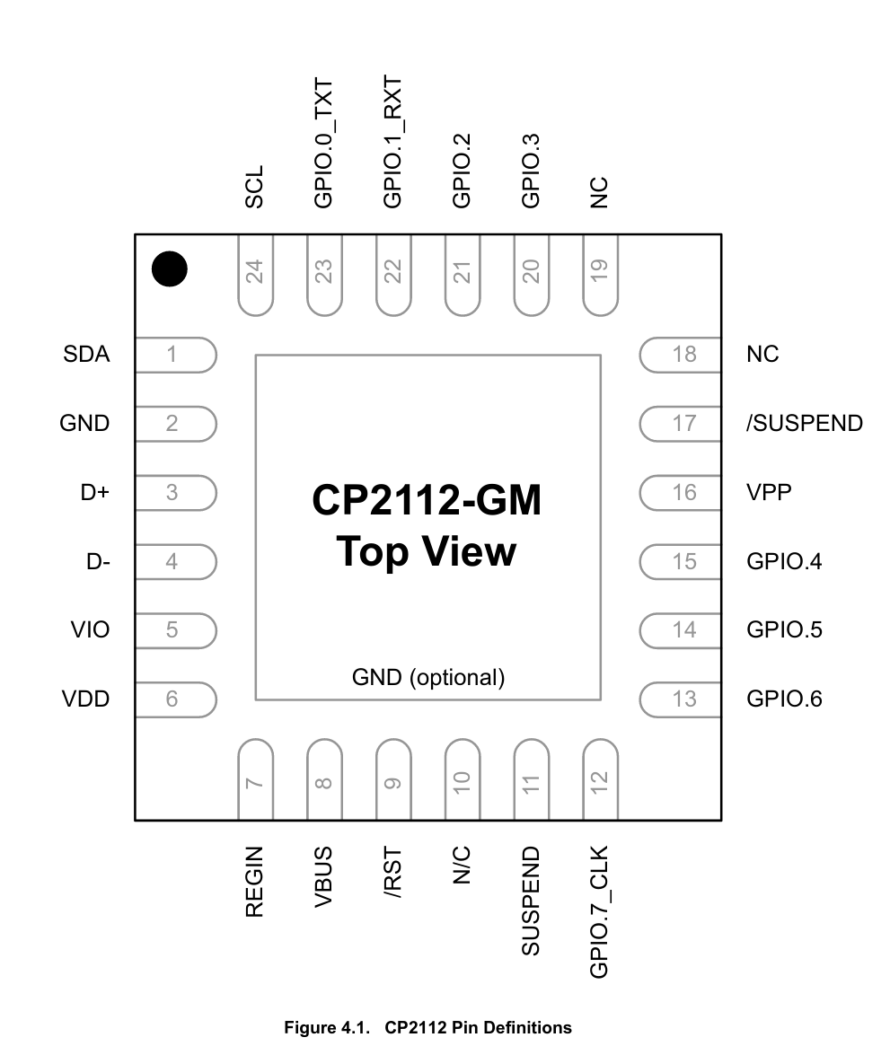
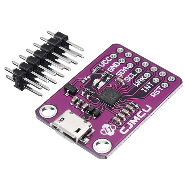 Its a pretty nice USB to I2C Board using Silicon Labs CP2112 chip.
Some nice featured
- I2C pins
- 8 gpios
- Activity leds (uses GPIO0, GPIO1)
- Configurable clock out 48 MHz to 94 kHz. (uses GPIO7) (Has quite alot of jitter)
- Switchable between 3.3v and 1.8v IO level!!!
- Upstream Linux kernel driver (provides /dev/{i2c-X,gpiochipX})
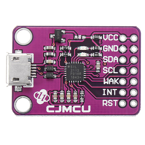
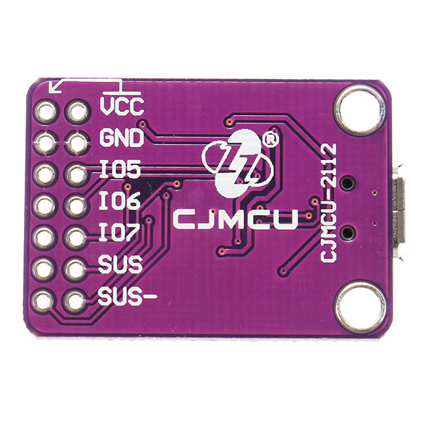
¶ Pinout
View from top down
| Left | Right | ||
|---|---|---|---|
| VCC | VCC | ||
| GND | GND | ||
| SDA | IO5 | GPIO.5 | |
| SCL | IO6 | GPIO.6 | |
| GPIO.2 | WAK | IO7 | GPIO.7_CLK |
| GPIO.3 | INT | SUS | |
| GPIO.4 | RST | SUS~ |
GPIO.0 and GPIO.1 are connected to the leds
¶ Switching from 3.3v to 1.8v
This is not really documented anywhere but..
Just swap the 000 0Ω resitor next to VCC pin to R1 place and you should be good to go.
Long version:
On this CP2112 board is configured to be bus powered. REGIN is connected to USB 5V and VDD pin provides 3.3v via integrated regulator. VIO pin sets the IO voltage level and is by default connected to VDD via 0Ω resistor. CJMCU board also has 65KU 1.8v regulator on board that can be connected to VIO pin via 0Ω jumber restor R1.

GIMP file of the traced schematic
¶ More images